| Problem | Solution |
|---|---|
| 20V, 2.1 A, not turning on | U7100, PROG1 250 Ω short – replace U7100. |
| Charger at 5 V, 0.000 A draw—no power draw | PP3V3_G3H is most likely shorted to ground with a 0–1 Ω short, most likely due to bad capacitor. When PP3V3_G3H is directly shorted to ground, it won't produce heat—the PP3V3_G3H power IC is smart enough, usually, when it detects a straight 0 Ω short, to just turn off. |
| 20 V, 0 A, not turning on, no shorts |
|
| Random crashing | No answer. This may be worth looking into. An extremely modest guy who wishes to remain anonymous along with Jake Hall and Matt Bone on the FB Logic board group have had success by inspecting and/ or replacing U7410 U7420 and U7430 and U7220 / U7370. Full post here (members only sorry, but join :) https://tinyurl.com/52t6vp2v ) Note boards are 2016/820-00875 and 2017/820-00840 |
| No power, charger at 20 V and 40 mA |
|
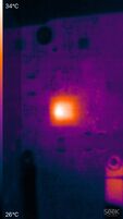
| No power, charger at 20 V and 40 mA | Short to ground on PP1V_S5G, a lot of short to ground around R8060 and those lines are link to the CPU, damn it's repairable ? Check with thermal camera and U7800 is hot (cf. pictures). Remove this guy, still short to ground, check all pads, a lot of rails related to the CPU is short, damn not repairable. Try a reflow if you're believer.
|
| No power, charger at 20 V taking 20 mA |
Example: https://www.youtube.com/watch?v=jYa7KaPkZvg (19–20 mA draw, 0.7 Ω short to ground on PPBUS_G3H caused by bad capacitor, 1 Ω resistor of current sensing circuit from U7000 (ISL9239) also blown)
Example: https://www.youtube.com/watch?v=ssTL3pKda54 (Short to ground on PP3V3_S4, PPBUS_G3H 13.7 V, bad capacitor, also damage to USB-C port, replaced CD3215 + other problems) Power cycling 10–30 mA at 20 V: Check for short to ground on PP5V_S4 |
| No power, PPBUS_G3H shorted to ground | Inject 1 V (increase if no reaction), watch for hot spots with thermal cam. Usually it's a bad tantalum cap on the PPBUS_G3H rail. Example: https://www.youtube.com/watch?v=PDKlWu1eDFA (Taking 20 V, 0 A. Ethanol used instead of thermal cam with 0.8 V on PPBUS_G3H, resistance between PPBUS_G3H and CPU coil is 3.6 Ω) Example 2: https://www.youtube.com/watch?v=TZsvvUWUInE (Taking 20 V, 20 mA. Bad capacitor located via visual inspection) Read the resistance from PPBUS_G3H to vCORE coils (coils around CPU/GPU) IF those measure UNDER 1 Ω (0.3–0.8) then you most likely have a direct 12 V short to CPU/GPU. On this board this situation is always a no fix. |
| No power on, 19.5 V 350 mA constant power draw |
|
| Charger stuck at 5 V instead of 20 V |
Example: https://www.youtube.com/watch?v=gBAZCUShuU4 (board taking 35 mA, 160 Ω short on PPVIN_G3H_P3V3G3H (input PP3V3_G3H creation circuit), fixed by replacing 3 capacitors and 1 diode)
Example: https://www.youtube.com/watch?v=myhB6dcm5lE (device not turning on, charger taking 0 mA)
Example: https://www.youtube.com/watch?v=nX7RwlTbHTQ (PP3V3_G3H 0.3 V, resistance to ground measured as 380 kΩ, active short caused by pi3usb32, found by using thermal camera) |
| Charger not turning on USB-C ammeter at all | Check PP20V_USBC for each port's resistance to ground.
Example: https://www.youtube.com/watch?v=ssTL3pKda54 (damage to USB-C port, also replaced CD3215 + other problems) |
| Battery not recognized | First, try a known good battery. If it doesn't work, check the battery cable going to the board. Sometimes there is corrosion here, sometimes the customer tore the bar on the connector off the connector. In some rare cases the SMC still is a factor in battery recognition on this board. |
| No backlight | Make sure the issue is no backlight, and not no image!
Example: https://www.youtube.com/watch?v=vOQ0fb9M2m4 (0 V on backlight circuit, 59 Ω short to ground caused by bad capacitor)
|
| No image | Check the LCD cable and the connector on both the screen side and the logic board side. The backlight power line is right next to the eDP data line for the image. Any minor corrosion here results in 30 volts or more going to the CPU data line. This we have no solution for since replacing the CPU isn't economically viable. It can be a bad GPU inside the CPU, which we have no solution for. |
| Laptop starts to S0 state but no image and no working USB. There is no end to the EIF procedure | Laptop in S0 state but draws 100–200 mA, backlight present but no image. The damaged U2800 blocks the start - in 90% of cases it needs to be replaced.
|
| Kills USB-C devices | Make sure that 20 V is only present on C3101 OR C3201 (PP20V_USBC_XA_VBUS OR PP20V_USBC_XB_VBUS). If A is making 20 V on B, or vice versa, likely need to replace the MOSFETs Q3100 and/or Q3200, since they're letting 20 V through (backwards!) when they're not supposed to. |
| USB devices not working when plugged in although charger works | This board has a USB redriver chip which is not present in the schematic and boardview. It is located right next to the USB connector, on the opposite side from the CD3215s, next to U2800. Marking on the chip is PI3USB32224BXEAE. If it dies, it prevents USB communication with devices. Often times you can see a hole on the chip. |
| Potential no power in the future | Stress fractures on the TPS51980 joints, similar to U8900 issues on the 820-3332. In time we may start seeing these come in dead for no reason and all it needed was reflow of TPS51980. On pin 25 there is already a hairline fracture. Pins 17, 18, and 19 look like they are getting stressed. See here: https://wiki2.rossmanngroup.com/index.php?title=File:820-00840_TPS51980_bad_joints_01.jpg https://wiki2.rossmanngroup.com/index.php?title=File:820-00840_TPS51980_bad_joints_02.jpg https://wiki2.rossmanngroup.com/index.php?title=File:820-00840_TPS51980_bad_joints_03.jpg https://wiki2.rossmanngroup.com/index.php?title=File:820-00840_TPS51980_bad_joints_04.jpg |
| No Wi-Fi on liquid damaged board | Removed liquid damage, still no Wi-Fi. Solution: U3780, the Wi-Fi ROM died. Replaced, works! |
| No audio, sound card not showing up in system |
|
| Charger stuck at 5 V, about 20 mA current. Board has liquid damage. | No rails are shorted, PP3V3_G3H present Remove the shield over U2800, clean and inspect all components around it, reflow if necessary. |
| No PPBUS_G3H power, charger stuck at 20 V and 34–36 mA | No PPBUS_G3H. Replaced Q7030 and U7000 (ISL9239HI with ISL9239C0) without any changes to the fault. With a partially charged battery, the logic board would offer fan spin and briefly show the battery icon to request the charger to be plugged in. The official power adapter (Type C) would not charge this new battery with 1 charge cycle (vendor supplied). The root cause was with SMB_SMC_CHGR_SDA. Voltage on SMB_SMC_CHGR_SDA was at 0.8 V while SMB_SMC_CHGR_SCL was at 3.3 V when the logic board was powered. Checked the local pull-up resistors being present for this SMBUS shared bus (R5380, R5381). Each was being pulled up to the PP3V3_G3H rail (3.42 V). All correct. The faulty component causing this stuck SMB_SMC_CHGR_SDA line was at D6950. This TVS diode must have been leaking. Upon removal off the logic board, the resistance to ground for both the SCL and SDA lines increased. Powering up, the PPBUS_G3H returned to normal and now the logic board is booting and charging the new battery. In hindsight, do not believe that U7000 nor Q7030 required to be replaced. The SEMTECH RCLAMP3552T part at D6950 is available from Arrow and other distributors. |
| No power, charger at 20 V and 565 mA |
|
MacBook Pro 13" · Intel
A1708 2016, 2017 13” USB-C non-touchbar MacBook Pro
Text original în engleză, salvat de pe old.repair.wiki · licență CC BY-SA · autori: contributorii repair.wiki
Nu e scris de noi. Conținutul de mai jos aparține contributorilor repair.wiki și e republicat liber, sub aceeași licență, ca să nu se piardă. Nu ne asumăm creditul.
Presupune schemă, boardview și experiență în microsudură. Despre arhivă →
Alte modele MacBook Pro 13" din arhivă
- A1502 2013-2014 13” MacBook Pro Retina
- A1502 2015-2016 13” MacBook Pro Retina
- A1706 2016-2017 13” Touchbar MacBook Pro
- A1989 2018 13” Touchbar MacBook Pro
Nu vrei să o repari singur?
Exact pe procedurile astea lucrăm la reparațiile de placă de bază: MacBook Pro A1708 inclus. Diagnostic aprofundat 180 lei, inclus în prețul reparației.