A2442 Information Page (Voltages, Diode mode readings, resistance readings and observations.)
| Problem | Solution |
|---|---|
| No light on the Magsafe 3 charger, 5v / 0.00 - 0.02 amps as measured by a USB-C amp meter at the base of the charger. | Differential diagnosis for no light on the Magsafe 3 charger with very low amp draw (0.00-0.02) • PPBUS_AON missing, low or shorted to ground. • PP3V8_AON missing, low or shorted to ground |
| Functioning RAA209100B | For those who want to know how UP800 works, here is the datasheet that comes closest. https://www.mouser.fr/datasheet/2/698/REN_isl95338_DST_20190619-1998566.pdf |
PRELIMINARY ONLY - FINAL TO FOLLOW
Testing performed on a 2021 A2442, with the 8 Core M1 Pro CPU with 16GB of RAM and 512GB of SSD storage.
Observations:
The device will auto start, run and boot fully off the MagSafe 3 power adapter with the battery disconnected.
The device will boot fully without the trackpad connected.
As with previous devices, the trackpad acts as the "brain" for the keyboard, and the keyboard will not function without the trackpad connected.
As with previous devices, the palmrest thermal sensor is located on the trackpad and hence the fans will run at full if the trackpad is disconnected or otherwise is failed in a way that prevents SMBUS communication with the system board.
Voltages:
Measured with a FLIR DM166 Multimeter.
PPBUS_AON: (With a fully charged battery connected, charger disconnected.) - ~12.60v
PPBUS_AON (Battery unplugged, with Magsafe 3 cable connected.) - ~12.00
820-02098 Power Sequence
SUBJECT TO CHANGE AS MORE INFORMATION IS LEARNED ABOUT THE NEW GENERATION OF DEVICES.
As of 11/26/21, Power sequence as measured with the board out of the enclosure.
!!!The device must be connected to the Magsafe 3 charger when the battery is disconnected to start and run off the charger. The device will not start and will not run off of a USB-C charger with the battery disconnected.!!!
PPDCIN_AON - ~ 20v. Measurable on the tantalum capacitors below the ISL9240. (See photo below for reference.)
Diode mode reading: 0.500
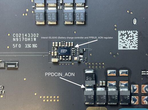
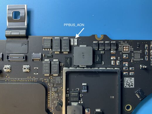
PPBUS_AON - ~ 12.00v. Measurable on the 2 fuses at the edge of the board, adjacent to the battery flex marked "12." (See photo below for reference.)
Diode mode reading: 0.430
PPBUS_AON is created by the ISL9240, which acts as a buck or boost converter depending on its input voltage. See above photo for reference on the location of the ISL9240 on this board.
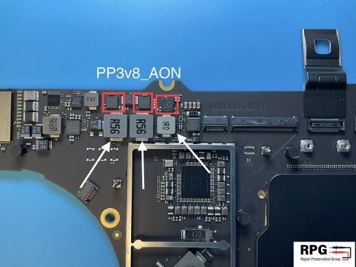
PP3v8_AON - ~ 3.8v. Measurable on the 3 inductors adjacent to the keyboard backlight and keyboard connectors. (See photo below for reference.)
Diode mode reading: 0.305
PP3v8_AON is created by a Renesas 501CR17 gate driver that drives 3 MOSFETs located directly above the inductors (MOSFETs marked in red in the reference photo below.) . The Renesas 501CR17 is located directly below the 3 inductors on the other side of the board. The chip is covered by a thermal sticker. PP3v8_AON has 3 phases (As seen with the 3 inductors) which all feed into the same line. This suggests a high current demand.
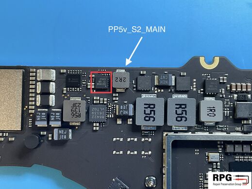
PP5v_S2_MAIN - ~ 5.0v. Measurable on the small inductor adjacent to the PP3v8_AON generation circuit. ( See photo for reference.)
Diode mode reading: 0.350
PP5v_S2_MAIN is created by a Texas Instruments TPS62130B. (Marked in red)
Viper Power Stages (Likely powers the CPU/GPU execution cores.)
PP1v8_S1_CLVR_VDDH - ~1.8v. Measurable on 3 inductors located under the 2 large shields on the top side of the board. (See photo for reference.)
Diode mode reading: 0.070
PP1v8_S1_CLVR_VDDH is a 3 phase power rail, generated by 3 Renesas 225701C VRMs (Marked in red), driven by a Renesas 502CR0E gate driver (Marked in red on the bottom picture.) which is located on the opposite side of the board.
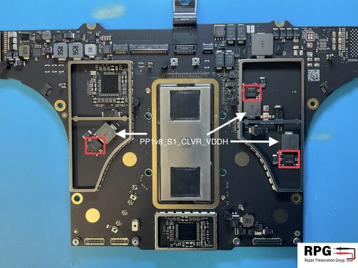
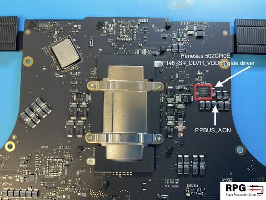
The majority of the rest of the systems main power rails (Including those that power the CPU and RAM, are outputted by 2 Apple-Designed PMICs marked APL 1098. Both of the PMICs are of the same type, and likely compatible with each other for replacement.
Measurements
Download the PNG file and import into Draw.io tool to edit Online/Offline if needed. Then PNG can be re-uploaded. This way everybody can add information as needed. [1]
A2442 TPS62180 ELC180 - SSD corner Side - diode-measurements
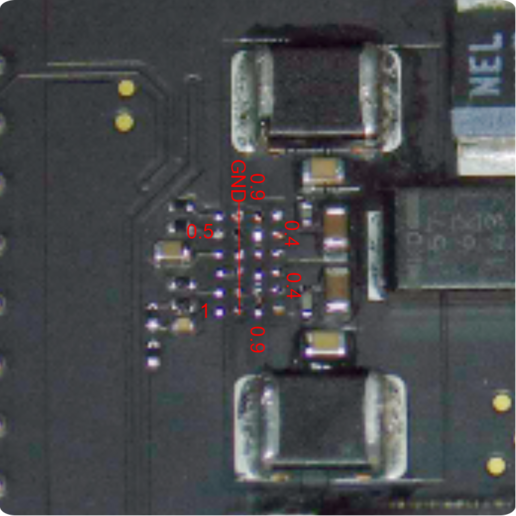
- ↑